Get Start
Install USB Driver
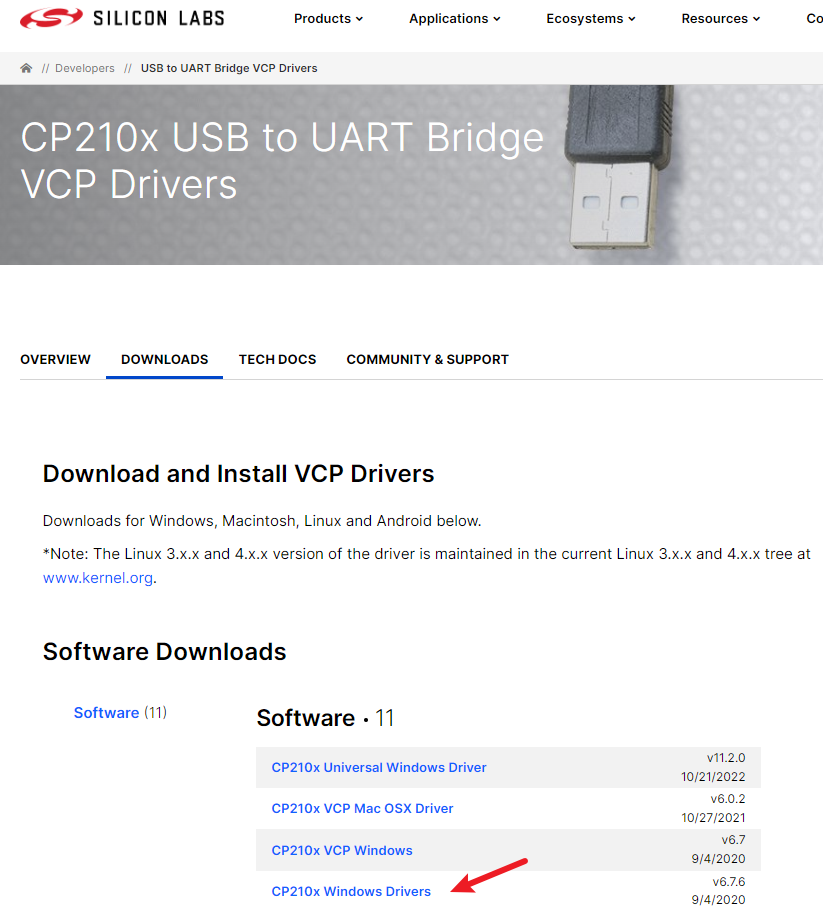
The ESP32-DevKitC SY-8 board USB to UART Chip is CP2102. If your PC has not installed the driver, you will need to download the USB driver and install it first.
If your computer has install the USB driver, you can jump this step.
The driver download link is: https://www.silabs.com/developers/usb-to-uart-bridge-vcp-drivers?tab=downloads
Note
The downlink may be changed, you can use google to the wordCP2102 driver to find the right download link.
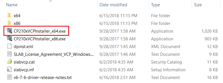
Extract the .zip file, then you will see the files like below, click CP210xVCPInstaller_x64.exe to install the driver.
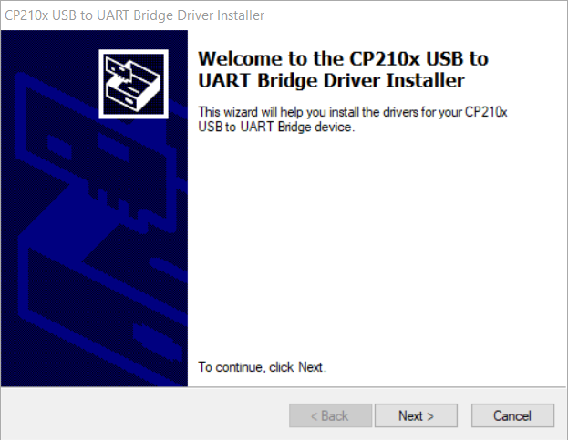
Flow the installation instructions to install the driver.
After the USB to UART driver is installed, connect the ESP32 board to the PC. There should be a notice sound from the PC while plugging in the connector PC.
Search and open the device manager
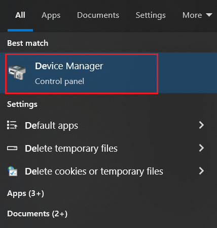
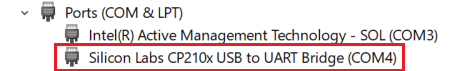
Under the tree of Ports (COM & LPT it should find a device named Silicon Lab CP210x USB to UART Bridge (COMx). The COMx means it is mounted as which com port in this PC, this time. Show as below picture, here is COM4
Warning
There are some mini USB cables that just contain 2 wires used for power. It is not able to transfer data between the development board and PC. So please make sure the USB cable is with data wires.
Now you have installed USB driver to your computer, and the computer is able to idetify the development board. That means you can communicate with the development board and your computer.
Install Development IDE
In this section we will guide you to install a development IDE to wirte code, build the code and flash it onto the development board.
Actually, this ESP32 board support Arduino platform, so any Audino supported IDE is able to be used for it. Here we recommond the PlatformIO tool for you. Please follow this instructions to install Platform IO.
First LED Flash Code
Edit the main.cpp file, the content is like below:
#include <Arduino.h>
const int ledPin = 2;
void setup()
{
  // put your setup code here, to run once:
  // setup pin 5 as a digital output pin
  pinMode(ledPin, OUTPUT);
}

void loop()
{
  // put your main code here, to run repeatedly:
  digitalWrite(ledPin, HIGH); // turn on the LED
  delay(500);                 // wait for half a second or 500 milliseconds
  digitalWrite(ledPin, LOW);  // turn off the LED
  delay(500);                 // wait for half a second or 500 milliseconds
}
Then build and upload the code to ESP32 development board.
Our development board support auto download or flash, so just wait, after uploaded, it will auto reset the board, then the new code is running on the development board.
Now you can see the blue LED on the board is flasing!
Great!
Take quite a long tour, you can contorl the development board now, it's worth, right?