Overview
This guide shows how to start using the ESP32 DevKit C Based Development bard SY-8.
What You Need
- ESP32-DevKitC SY-8 board
- USB A to micro USB B cable
- Computer running Windows, Linux, or macOS
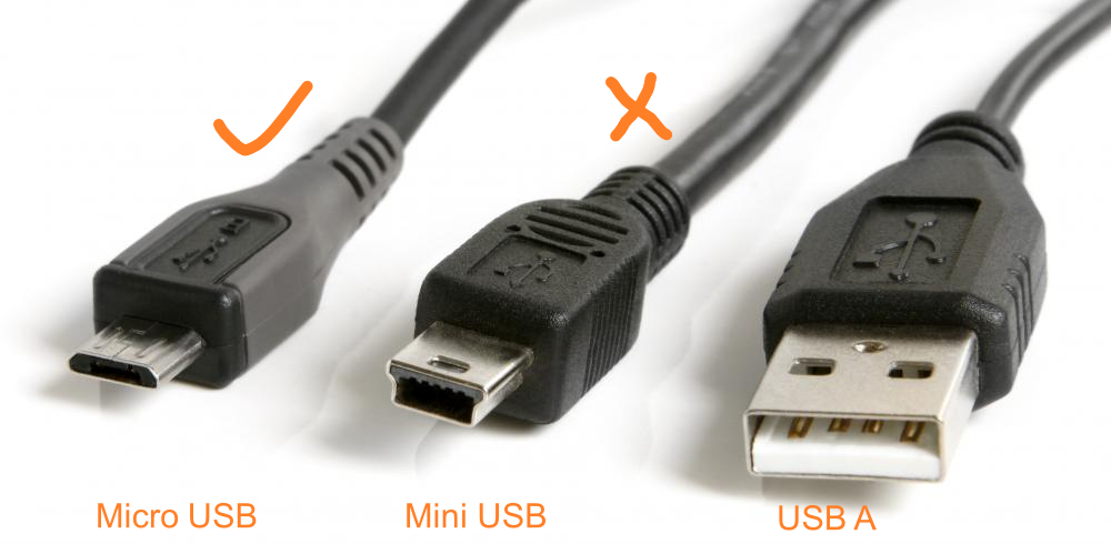
If you are not sure what the USB cable is, ref to below picture for the USB connector names.
Main Features
ESP32-DevKitC SY-8 development board is an ESP32-based development board produced by Seeyouart.
- It base on ESP32 module ESP32-WROOM-32E.
- Support devoloped with Arduino, PlatformIO, FreeRTOS, MicroPython.
- Support Wifi, Bluetooth.
- Auto flash download. No need to press EN or BOOT button to start flashing.
Hardware on Board
The following figure and the table below describe the key components, interfaces of the ESP32-DevKitC SY-8 board.

| Key Component | Description |
|---|---|
| ESP32-WROOM-32 | A module with ESP32 at its core. For more information, see ESP32-WROOM-32 Datasheet. |
| EN Button | Reset button. |
| Boot Button | Download button. |
| USB-to-UART Bridge | Single USB-UART bridge chip provides transfer rates of up to 3 Mbps. |
| Micro USB Port | USB interface. Power supply for the board as well as the communication interface between a computer and the ESP32-WROOM-32 module. |
| 5V Power On LED | Turns on when the USB or an external 5V power supply is connected to the board. For details see the schematics inRelated Documents. |
| I/O | Most of the pins on the ESP module are broken out to the pin headers on the board. You can program ESP32 to enable multiple functions such as PWM, ADC, DAC, I2C, I2S, SPI, etc. |
| 5V to 3.3V LDO | LDO to convert 5.5V Vin or Vusb to 3.3V |
| LED to IO2 | A blue LED connected to IO2 |
Power Supply Options
There are three mutually exclusive ways to provide power to the board:
- Micro USB port, default power supply
- or 5V / GND header pins
- or 3V3 / GND header pins
Warning
The power supply must be provided usingone and only one of the options above , otherwise the board and/or the power supply source can be damaged.
Header Block
There is a connector on each side of the board, the Name and Function of each pin shows as following:
J2
| No. | Name | Type | Function |
|---|---|---|---|
| 1 | 3V3 | P | 3.3 V power supply |
| 2 | EN | I | CHIP_PU, Reset |
| 3 | VP | I | GPIO36, ADC1_CH0, S_VP |
| 4 | VN | I | GPIO39, ADC1_CH3, S_VN |
| 5 | IO34 | I | GPIO34, ADC1_CH6, VDET_1 |
| 6 | IO35 | I | GPIO35, ADC1_CH7, VDET_2 |
| 7 | IO32 | I/O | GPIO32, ADC1_CH4, TOUCH_CH9, XTAL_32K_P |
| 8 | IO33 | I/O | GPIO33, ADC1_CH5, TOUCH_CH8, XTAL_32K_N |
| 9 | IO25 | I/O | GPIO25, ADC1_CH8, DAC_1 |
| 10 | IO26 | I/O | GPIO26, ADC2_CH9, DAC_2 |
| 11 | IO27 | I/O | GPIO27, ADC2_CH7, TOUCH_CH7 |
| 12 | IO14 | I/O | GPIO14, ADC2_CH6, TOUCH_CH6, MTMS |
| 13 | IO12 | I/O | GPIO12, ADC2_CH5, TOUCH_CH5, MTDI |
| 14 | GND | G | Ground |
| 15 | IO13 | I/O | GPIO13, ADC2_CH4, TOUCH_CH4, MTCK |
| 16 | D2 | I/O | GPIO9, D22 |
| 17 | D3 | I/O | GPIO10, D32 |
| 18 | CMD | I/O | GPIO11, CMD2 |
| 19 | 5V | P | 5 V power supply |
J3
| No. | Name | Type1 | Function |
|---|---|---|---|
| 1 | GND | G | Ground |
| 2 | IO23 | I/O | GPIO23 |
| 3 | IO22 | I/O | GPIO22 |
| 4 | TX | I/O | GPIO1, U0TXD |
| 5 | RX | I/O | GPIO3, U0RXD |
| 6 | IO21 | I/O | GPIO21 |
| 7 | GND | G | Ground |
| 8 | IO19 | I/O | GPIO19 |
| 9 | IO18 | I/O | GPIO18 |
| 10 | IO5 | I/O | GPIO5 |
| 11 | IO17 | I/O | GPIO173 |
| 12 | IO16 | I/O | GPIO163 |
| 13 | IO4 | I/O | GPIO4, ADC2_CH0, TOUCH_CH0 |
| 14 | IO0 | I/O | GPIO0, ADC2_CH1, TOUCH_CH1, Boot |
| 16 | IO2 | I/O | GPIO2, ADC2_CH2, TOUCH_CH2 |
| 17 | IO15 | I/O | GPIO15, ADC2_CH3, TOUCH_CH3, MTDO |
| 17 | D1 | I/O | GPIO8, D12 |
| 18 | D0 | I/O | GPIO7, D02 |
| 19 | CLK | I/O | GPIO6, CLK2 |
1(1,2)P: Power supply; I: Input; O: Output.
2(1,2,3,4,5,6)The pins D0, D1, D2, D3, CMD and CLK are used internally for communication between ESP32 and SPI flash memory. They are grouped on both sides near the USB connector. Avoid using these pins, as it may disrupt access to the SPI flash memory / SPI RAM.
3(1,2)The pins GPIO16 and GPIO17 are available for use only on the boards with the modules ESP32-WROOM and ESP32-SOLO-1. The boards with ESP32-WROVER modules have the pins reserved for internal use.
Pin Layout
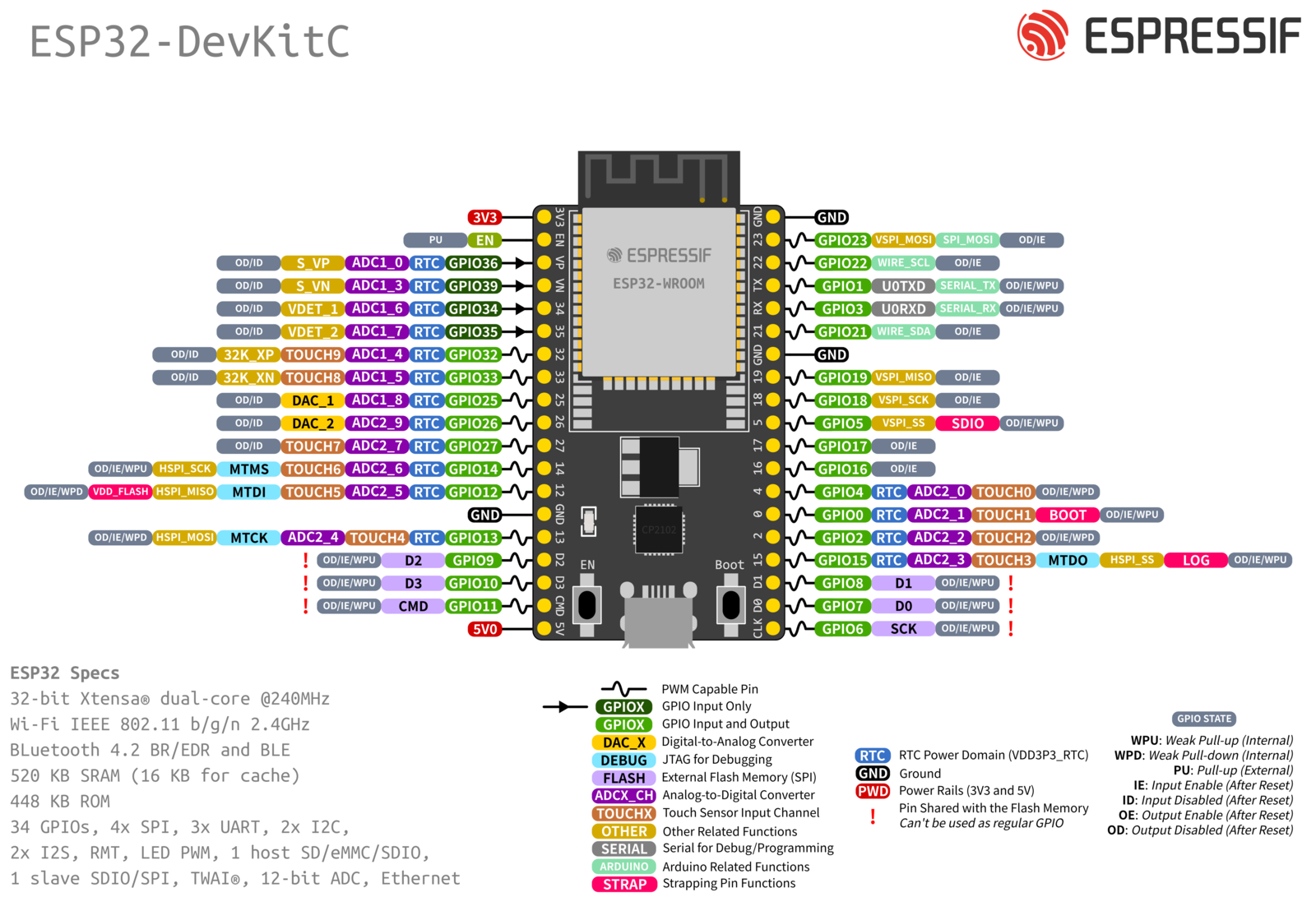 ESP32-DevKitC Pin Layout (click to enlarge)
Start Application Development
Before powering up your ESP32-DevKitC V4, please make sure that the board is in good condition with no obvious signs of damage.
After that, proceed to Get Started, where Section Installation will quickly help you set up the development environment and then flash an example project onto your board.
Board Dimensions
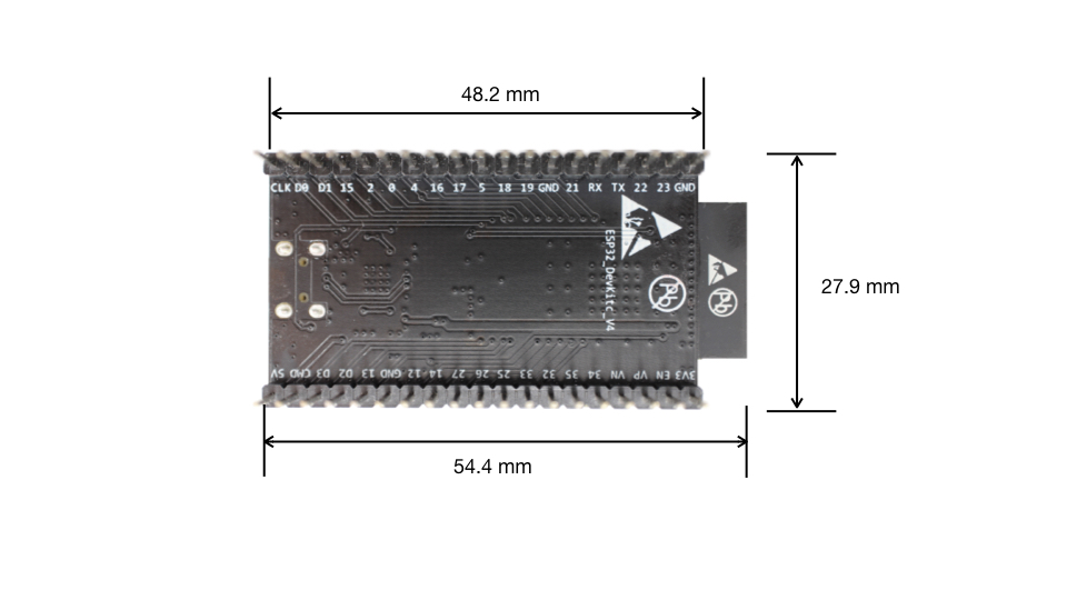 Dimensions of ESP32-DevKitC board with ESP32-WROOM-32 module soldered - back (click to enlarge)
Related Documents
- ESP32 Datasheet (PDF)
- ESP32-WROOM-32 Datasheet (PDF)
- ESP32-WROOM-32D and ESP32-WROOM-32U Datasheet (PDF)
For further design documentation for the board, please contact us at sales@seeyouart.com.