ESP32 PWM Output
This article is to explain how to use the ESP32's PWM (Pulse Width Modulation) functionality to achieve changes in LED brightness.
Introduction
The ESP32 Arduino environment does not yet provide the commonly used analogWrite Arduino function. Therefore, we need to use low-level functions as demonstrated in this tutorial. However, this gives us more control and flexibility in terms of PWM, which is good news.
In terms of hardware, the ESP32's LED PWM consists of 16 independent channels with configurable duty cycles and wave periods. The precision of the duty cycle can be configured up to a 16-bit resolution.
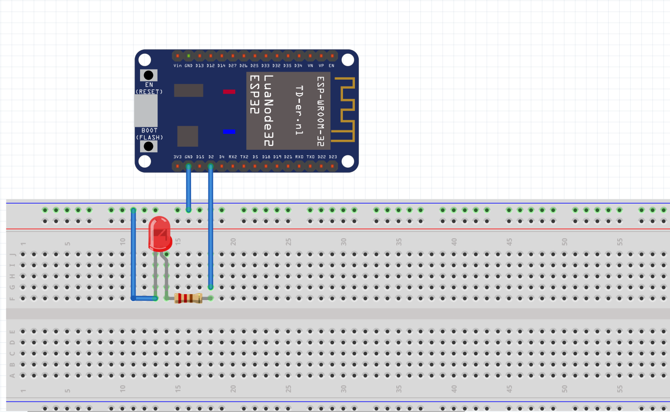
Components List
- ESP32 development board
- One LED (I'm using a 5mm red LED)
- Breadboard
- Several jumper wires
Circuit Diagram
Code Design
1. Initialization Setup
In the first part of the code, we define some global configuration constants. The first one is the frequency of the PWM signal generated for controlling the LED. We will use a value of 5000Hz. However, note that the maximum frequency is not clear yet, and the maximum frequency depends on the selected resolution, as declared in the header file of the function we are going to use.
We will specify the LED PWM channel and the resolution in bits. Also, from the header file, we can see that we can choose a channel between 0 and 15, and a resolution between 1 and 16 bits. Here, we will use channel 0 and an 8-bit resolution.
int freq = 5000;
int ledChannel = 0;
int resolution = 8;
Next, in the setup function, we configure the LED PWM. First, we need to set the channel, frequency, and resolution that we specified. We do this by calling the ledcSetup function, which takes the three parameters mentioned above in the same order.
ledcSetup(ledChannel, freq, resolution);
However, it's important to note that the channel is not the GPIO pin that controls the LED. Thus, we need to connect channel 0 (the one we defined) to the digital GPIO pin where we want to generate the PWM signal. In my case, I'm connecting it to GPIO pin 2. We use the ledcAttachPin function, passing the GPIO pin number and the previously defined PWM channel as arguments.
ledcAttachPin(2, ledChannel);
Here's the complete initialization setup along with constant definitions:
#define LED_PWM 2 // Define the GPIO pin being used for the call
int freq = 5000;
int ledChannel = 0;
int resolution = 8;
void setup() {
    ledcSetup(ledChannel, freq, resolution);
    ledcAttachPin(LED_PWM, ledChannel);
}
2. In the Main Loop
We will write code to control the duty cycle value of the signal in the Arduino main loop. The most important function for allowing us to specify the duty cycle value is the ledcWrite function, which takes the PWM channel (not the GPIO number) as its first parameter.
Since we defined an 8-bit resolution, we can specify duty cycle values between 0 and 255 (which is 2^8 - 1). Therefore, we iterate through these values in two loops, one incrementing and the other decrementing. The following is the complete source code, including calls to the ledcWrite function and these two loops.
/*******************************************************
   ESP32 PWM Breathe LED
   Function: Achieve LED breathing effect
   Pin: D2 (GPIO2)
*******************************************************/

#define LED_PWM 2 // Define the GPIO pin being used for the call
int freq = 5000;
int ledChannel = 0;
int resolution = 8;

void setup() {
    ledcSetup(ledChannel, freq, resolution);
    ledcAttachPin(LED_PWM, ledChannel);
}

void loop() {
    for (int dutyCycle = 0; dutyCycle <= 255; dutyCycle++) {
        ledcWrite(ledChannel, dutyCycle);
        delay(7);
    }
    for (int dutyCycle = 255; dutyCycle >= 0; dutyCycle--) {
        ledcWrite(ledChannel, dutyCycle);
        delay(7);
    }
}
Testing the Code
To test the code, simply upload it using the Arduino IDE. You should then see the LED breathing effect. The following video demonstrates the effect:
![]()