When we start play with a new hardware develop board, the first thing is make the LED blink. This never fails to excite us, and it's truly something worth showing off.
1. Component List
- ESP32 Development Board
- One LED (I used a 5mm red LED)
- One 220-ohm Resistor
- Breadboard
- Several Jumper Wires
By the way, let me explain how to choose the current-limiting resistor for the LED and set an appropriate resistance value. We can find relevant parameters for the LED in its datasheet. To calculate the current-limiting resistor for the LED, the most important parameters are: Forward Voltage (VF), Forward Current (IF), and Peak Forward Current.
The LED's forward current can be taken as the peak value. However, to keep the operating current below the limit, you can calculate the current-limiting resistor using the following formula:
Current Limiting Resistor = Power Supply Voltage - LED Forward Voltage / LED Forward Current
Of course, after calculating the resistance value for the current-limiting resistor, not all available resistor values in the market may match exactly. You need to choose a resistor that is close to the calculated value. After selecting a resistor value, recalculate to ensure that the LED's forward current and voltage remain within the limits.
Generally:
- Red and green LEDs have a voltage of 1.8-2.4V.
- Blue and white LEDs have a voltage of 2.8-4.2V.
- Rated current for 3mm LEDs is 1-10mA.
- Rated current for 5mm LEDs is 5-25mA.
- Rated current for 10mm LEDs is 25-100mA.
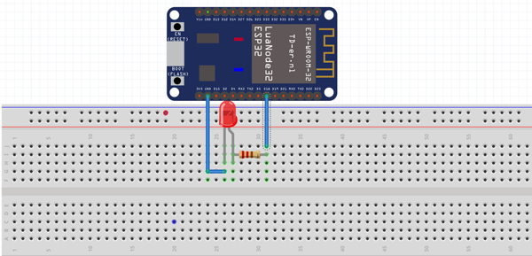
2. Circuit Connection

3. LED Blinking Code
/*******************************************************
   ESP32 LED Blinking
   Function: Blink the LED every second
   Pin: D18 (GPIO18)
*******************************************************/

int LED = 2;

void setup() {
  pinMode(LED, OUTPUT);
}

void loop() {
  digitalWrite(LED, HIGH); // Turn on the LED
  delay(1000); // Wait for a second
  digitalWrite(LED, LOW); // Turn off the LED
  delay(1000); // Wait for a second
}
When you see the above code, you'll notice that it's entirely identical to the ESP8266 and Arduino syntax. Yes, the syntax used in Arduino is compatible with ESP32. This similarity saves us a lot of effort when dealing with the ESP32.
Next, let's move on to creating our classic LED chaser.
2. LED Chaser Creation
1. Component List
- ESP32 Development Board
- Four LEDs (I used four 5mm red LEDs)
- Four 220-ohm Resistors
- Breadboard
- Several Jumper Wires
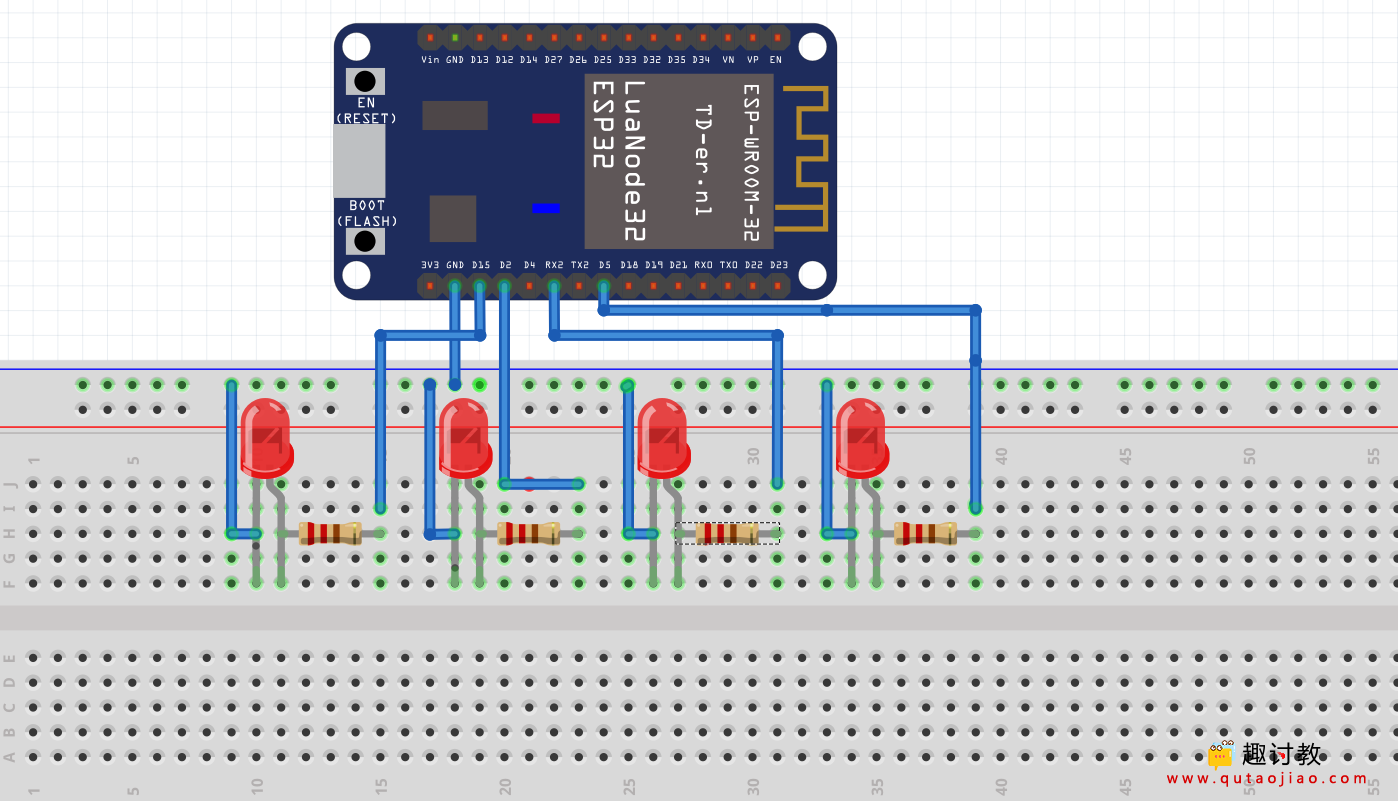
2. Circuit Connection

3. LED Chaser Code
/*******************************************************
   ESP32 LED Chaser
   Function: Sequentially light up four LEDs
   Pins: D15, D4, D2, D5
*******************************************************/

char LEDPins[] = {15, 4, 2, 5}; // Set the connected pins
int i = 0;
int L1 = 0;
int len = 0;

void setup() {
  len = sizeof(LEDPins) / sizeof(char); // Calculate array length
  for (i = 0; i < len; i++) {
    pinMode(LEDPins[i], OUTPUT); // Set pins as output
    digitalWrite(LEDPins[i], LOW); // Turn off LEDs
  }
}

void loop() {
  digitalWrite(LEDPins[L1], HIGH); // Turn on the current LED
  delay(100); // Wait for a short period
  digitalWrite(LEDPins[L1], LOW); // Turn off the current LED
  delay(100); // Wait for a short period
  L1 = L1 + 1; // Move to the next LED
  if (L1 > len || L1 < 0) // Check if reached the last or first LED
    L1 = 0; // Start from the beginning
}
By changing the number of GPIO