Overview
Pulse Width Modulation (PWM) is a technique that changes the pulse width while keeping the waveform frequency constant. PWM is primarily used for controlling the brightness of LEDs, the speed of DC motors, controlling servo motors, and any scenario where a digital source is needed to generate an analog signal.
PWM Terminology
Before diving into the PWM functionality on the ESP32, let's discuss some PWM-related terms:
- TON (On Time): The duration for which the signal is high.
- TOFF (Off Time): The duration for which the signal is low.
- Period: The sum of the TON and TOFF of a PWM signal.
- Duty Cycle: The percentage of time within a PWM signal period that the signal is high.
For example, if a 10ms pulse stays ON (high) for 5ms, then the duty cycle is:
Duty Cycle = 5/10 * 100% = 50%.
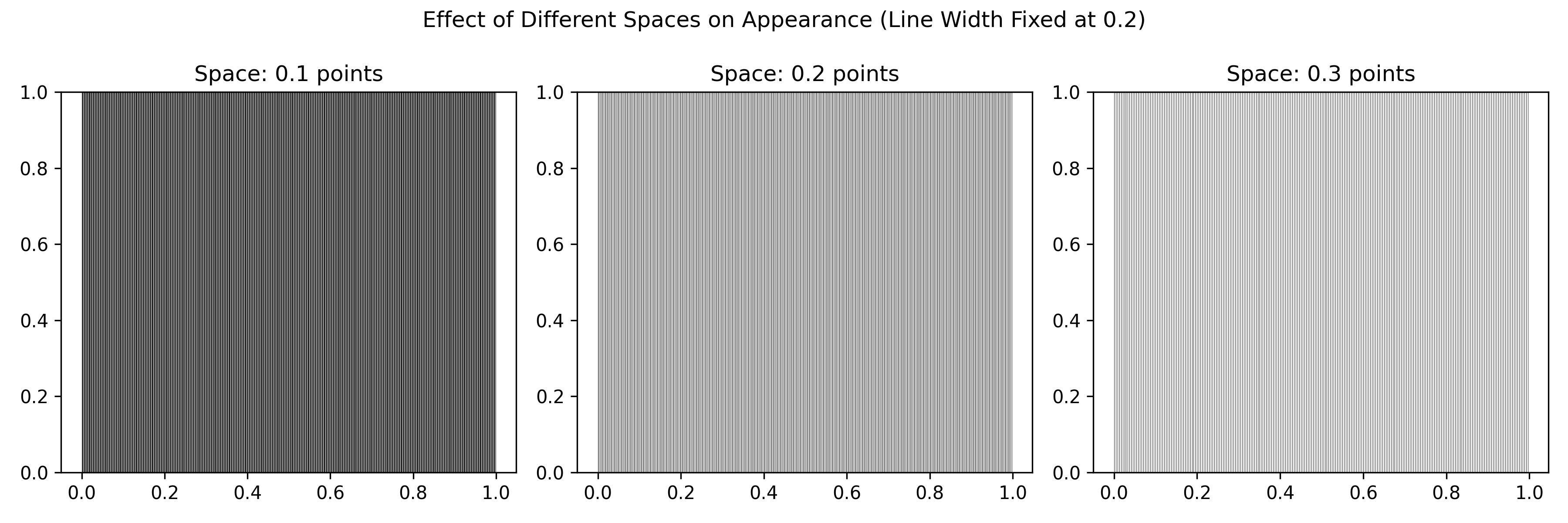
Here I make a example of to draw lines to demonstrate the PWM effect. The python code:
import numpy as np
import matplotlib.pyplot as plt

fig, axs = plt.subplots(1, 3, figsize=(12, 4))

# different space
spacing_points = [0.1, 0.2, 0.3]

# fix line width
line_width = 0.2

for ax, sp in zip(axs, spacing_points):
    x = np.arange(0, 1, sp / 72)
    y = 1
    ax.vlines(x, ymin=0, ymax=y, colors="black", linewidth=line_width)
    ax.set_ylim(0, 1)
    ax.set_title(f"Space: {sp} points")

plt.suptitle("Effect of Different Spaces on Appearance (Line Width Fixed at 0.2)")
plt.tight_layout()
plt.savefig("pwm.png", dpi=300)
plt.show()

The figure shows above, from left to right, the image changes from dark to light. Actually, they are draw by the same color and same width line, we feel the brightness are different is just because the lines with different space.
If turn on and off the LED at a high speed, then watch the LED, it will have the similar effect, but the longer the ON time, the brighter the LED.
ESP32 LED PWM Controller (LEDC)
The LEDC peripheral of the ESP32 consists of 16 PWM channels capable of generating independent waveforms, primarily used for RGB LED control, but can also be used for other purposes. There are a few interesting points you should note about the LED PWM controller in the ESP32.
- 16 independent PWM channels, divided into two groups of 8 channels each.
- Programmable resolution between 1 and 16 bits.
- The frequency of the PWM wave depends on the resolution of the PWM.
- Automatically increases/decreases duty cycle without processor intervention.
But using PWM in ESP32 is not as simple as that in Arduino development board. Some configuration is required to make it work.
Configure ESP32's PWM channels
In Arduino programming, the “analogWrite()” function is used to generate PWM signals. However, almost everything in the ESP32’s LED PWM requires user configuration (channels, resolution, and frequency), so we will use a different (and dedicated) set of functions to configure the PWM in the ESP32 instead of using the “analogWrite()” function.
Below is a list of all LEDC APIs exposed by the driver. These functions are written for the Arduino IDE port for the ESP32.
- ledcSetup(channel, frequency, resolution bits)_
- ledcAttachPin(pin, channel);
- ledcWrite(channel, duty cycle);
- ledcRead(channel);
- ledcWriteTone(channel, frequency)
- ledcWriteNote(channel, note, octave);
- ledcReadFreq(channel);
- ledcDetachPin(pin);
Of the 8 functions, we will focus on the first three, as they are more useful (and the minimum required) for generating PWM.
Some important points to remember when configuring PWM channels in ESP32:
- Since there are 16 PWM channels, the Channels parameter can take any value between 0 and 15.
- Next is the frequency of the PWM signal. You can set the frequency as per your requirement, such as 1 KHz, 5 KHz, 8 KHz and 10 KHz.
- The resolution of the PWM is also configurable, the ESP32 PWM can be programmed anywhere between 1 bit to 16 bits of resolution.
- PWM frequency and resolution are inversely proportional and depend on the clock source. Therefore, be careful when choosing frequency and resolution values.
- Finally, assign GPIO pins for PWM output. You can assign any GPIO pins, but be careful when assigning (do not use GPIO pins that are already in use, such as UART, SPI, etc.).
The following table shows some commonly used PWM frequencies and resolutions.
| LEDC Clock Source | LEDC PWM frequency | PWM resolution |
|---|---|---|
| 80 MHz APB_CLK | 1KHz | 16-bit |
| 80 MHz APB_CLK | 5KHz | 14-bit |
| 80 MHz APB_CLK | 10KHz | 13th |
| 8 MHz RTC8M_CLK | 1KHz | 13th |
| 8 MHz RTC8M_CLK | 8KHz | 10-bit |
| 1 MHz REF_Tick | 1KHz | 10-bit |
Achieve results
In this experiment, the LED light on the ESP32 development board will be used as a PWM-controlled LED light to achieve a breathing effect.
ESP32 board has an LED light and can be controlled via GPIO 2
Program Code
const int LEDPin = 2;  /* GPIO16 */

int dutyCycle;
/* Setting PWM Properties */
const int PWMFreq = 5000; /* 5 KHz */
const int PWMChannel = 0;
const int PWMResolution = 10;
const int MAX_DUTY_CYCLE = (int)(pow(2, PWMResolution) - 1);

void setup()
{
  // Configure PWM channel, frequency, and resolution
  ledcSetup(PWMChannel, PWMFreq, PWMResolution);
  // Attach the configured PWM channel to the specified pin
  ledcAttachPin(LEDPin, PWMChannel);
}

void loop()
{
  // Increase LED brightness using PWM
  for(dutyCycle = 0; dutyCycle <= MAX_DUTY_CYCLE; dutyCycle++)
  {
    ledcWrite(PWMChannel, dutyCycle);
    delay(3); // Delay to control the brightness change speed
  }

  // Decrease LED brightness using PWM
  for(dutyCycle = MAX_DUTY_CYCLE; dutyCycle >= 0; dutyCycle--)
  {
    ledcWrite(PWMChannel, dutyCycle);
    delay(3); // Delay to control the brightness change speed
  }
}
One of the important features of PWM in ESP32 is that all 16 channels can be configured independently, that is, each channel can have its own resolution and frequency.