ESP32 DEVKIT V1 Pin Referance
The first and most importance step for us to use a MCU is know what the peripherals and IOs it provided.
In this article, it will discuss the GPIO pin of ESP32 DevKit, we will know what it can do, and it can not.
!!! note
In this article, it will discuss the ESP Devkit with 30 pins. Other revision develop board may have differnt configureation.
The ESP32 DEVKIT in our Amazone store is looks like this:
The general describe of ESP32 DevKit GPIO as below table.
| Function | Description |
|---|---|
| 15 ADC channels | 15 channels of 12-bit SAR ADC’s. The ADC range can be set, in firmware, to either 0-1V, 0-1.4V, 0-2V, or 0-4V |
| 2 UART interfaces | 2 UART interfaces. Commonly referred to as UART0 and UART1. One is used to load code serially. |
| 25 PWM outputs | 25 channels can output PWM signal for LEDs or motors controlling. |
| 2 DAC channels | 8-bit DACs to produce analog voltages output. |
| 3 SPI interfaces | 3 SPI interfaces. |
| 1 I2C interfaces | 1 I2C interfaces |
| 9 Touch Pads | 9 GPIOs feature capacitive touch sensing. |
And notice that a single GPIO pin on the ESP32 can be configured to act as an ADC input, a DAC output, or a touchpad, depending on your needs.
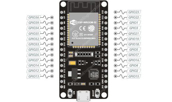
ESP32 DevKit Pinout
The ESP32 development board provides total 30 pins on two side of the board. It shows as below picture.
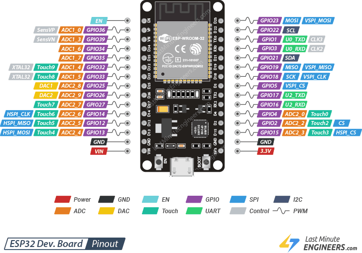
GPIO Pins
ESP32 development board has 25 GPIO pins which can be assigned to various functions programmatically. Each digital enabled GPIO can be configured to internal pull-up or pull-down, or set to high impedance.
Which ESP32 GPIOs are safe to use?
Because the ESP32 has many pins with specific functions, they may not be suitable for your projects. The following table shows which pins are safe to use and which pins require more attention before using them.
:material-check-circle:{ .success} Your first priority pins. They are perfectly
:material-alert-circle:{ .warning} Pay attention as their behavior can be unpredictable, mainly during boot. Don’t use them unless you absolutely need to.
:material-close-circle:{ .danger} It is not recommended to use these pins. So avoid them.
| Label | GPIO | Sign | Reason |
|---|---|---|---|
| D0 | 0 | :material-alert-circle:{ .warning} | Reset pin. LOW for boot load. must not be left floating, a pull-up resistor and a ground capacitor are highly recommended. |
| TX0 | 1 | :material-close-circle:{ .danger} | Tx pin, used for flashing and debugging |
| D2 | 2 | :material-alert-circle:{ .warning} | must be left floating or LOW to enter flashing mode, connected to the on-board LED |
| RX0 | 3 | :material-close-circle:{ .danger} | Rx pin, used for flashing and debugging |
| D4 | 4 | :material-check-circle:{ .success} | |
| D5 | 5 | :material-alert-circle:{ .warning} | must be HIGH during boot |
| D6 | 6 | :material-close-circle:{ .danger} | Connected to Flash memory |
| D7 | 7 | :material-close-circle:{ .danger} | Connected to Flash memory |
| D8 | 8 | :material-close-circle:{ .danger} | Connected to Flash memory |
| D9 | 9 | :material-close-circle:{ .danger} | Connected to Flash memory |
| D10 | 10 | :material-close-circle:{ .danger} | Connected to Flash memory |
| D11 | 11 | :material-close-circle:{ .danger} | Connected to Flash memory |
| D12 | 12 | :material-alert-circle:{ .warning} | must be LOW during boot |
| D13 | 13 | :material-check-circle:{ .success} | |
| D14 | 14 | :material-check-circle:{ .success} | |
| D15 | 15 | :material-alert-circle:{ .warning} | must be HIGH during boot, prevents startup log if pulled LOW |
| RX2 | 16 | :material-check-circle:{ .success} | |
| TX2 | 17 | :material-check-circle:{ .success} | |
| D18 | 18 | :material-check-circle:{ .success} | |
| D19 | 19 | :material-check-circle:{ .success} | |
| D21 | 21 | :material-check-circle:{ .success} | |
| D22 | 22 | :material-check-circle:{ .success} | |
| D23 | 23 | :material-check-circle:{ .success} | |
| D25 | 25 | :material-check-circle:{ .success} | |
| D26 | 26 | :material-check-circle:{ .success} | |
| D27 | 27 | :material-check-circle:{ .success} | |
| D32 | 32 | :material-check-circle:{ .success} | |
| D33 | 33 | :material-check-circle:{ .success} | |
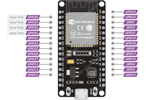
| D34 | 34 | :material-alert-circle:{ .warning} | Input only GPIO, cannot be configured as output |
| D35 | 35 | :material-alert-circle:{ .warning} | Input only GPIO, cannot be configured as output |
| VP | 36 | :material-alert-circle:{ .warning} | Input only GPIO, cannot be configured as output |
| VN | 39 | :material-alert-circle:{ .warning} | Input only GPIO, cannot be configured as output |
Input Only GPIOs
These pins cannot be configured as outputs:
- GPIO34
- GPIO35
- GPIO36(VP)
- GPIO39(VN)
they can be used as either digital inputs, analog inputs, or for other unique purposes. They do not have internal pull-up or pull-down resistors, like the other GPIO pins.
Also pins GPIO36(VP) and GPIO39(VN) are an integral part of the ultra-low-noise pre-amplifier for the ADC, which help to configure the sampling time and noise of the pre-amp.
Interrupt Pins
Any GPIO pin on the ESP32 can be used for interrupts.
Touch Pins
The ESP32 has a total of 10 internal capacitive touch sensors that can be used to detect touch input from user. These pins can be easily integrated into capacitive pads and replace mechanical buttons. The capacitive touch pins can also be used to wake up the ESP32 from deep sleep.
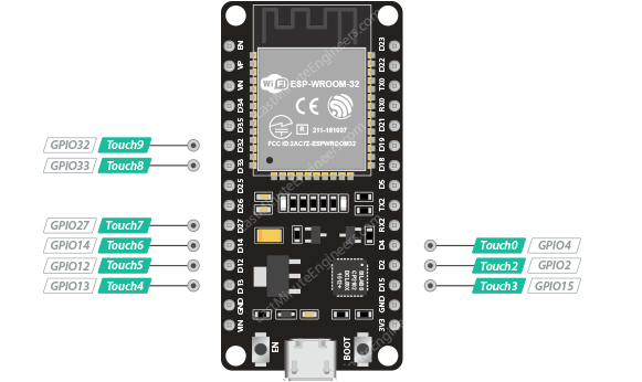
Those internal touch sensors are named as T0~T9, they according to these GPIOs:
- T0 (GPIO 4)
- T1 (GPIO 0)
- T2 (GPIO 2)
- T3 (GPIO 15)
- T4 (GPIO 13)
- T5 (GPIO 12)
- T6 (GPIO 14)
- T7 (GPIO 27)
- T8 (GPIO 33)
- T9 (GPIO 32)
ADC Pins
On the ESP32, there are several ADC (Analog-to-Digital Converter) channels that can be used to measure analog voltages and convert them to digital values.
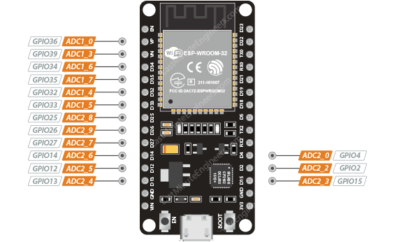
!!! warning
The ADC2 pins cannot be used when Wi-Fi is enabled. If your project plans to use Wi-Fi, consider choosing ADC1 pins.
ADC Resolution
On the ESP32, the ADC channels have a resolution of 12 bits, which means they can represent analog input values in the range of 0 to 4095 ($2^{12} - 1$) with increments of 1. This means that the analog input voltage can be measured with a resolution of approximately 0.8 mV (3.3V/4096) per step.
You can use the ESP32 Arduino core's analogRead() function to read the digital value of an analog input on one of the ADC channels.
It is important to note that the actual resolution of the ADC may be limited by other factors such as the noise and accuracy of the analog circuitry, as well as the stability and accuracy of the reference voltage used for the conversion.
It is recommended to add a 0.1 µF filter capacitor to a pad when using the ADC function.
The recommended input voltage of the ADC is below 2450 mV, and preferably within the range of 100 to
950 mV for higher calibration accuracy.
DAC Pins
On the ESP32, there are two DAC (Digital-to-Analog Converter) channels that can be used to convert digital values to analog voltages.
The specific DAC channels and the associated GPIO pins on the ESP32 are as follows:
- DAC1 (GPIO 25)
- DAC2 (GPIO 26)
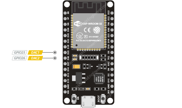
You can use the dacWrite() function to write a digital value to one of the DAC channels, which will be converted to an analog voltage and output on the corresponding GPIO pin.
It is important to note that the DAC channels on the ESP32 have a limited resolution and output range, and they may not be suitable for all analog output applications.
SPI pins
ESP32 integrates 4 SPI:
- SPI0 and SPI1 used to connect with the flash memory of the chip. SPI0 and SP1 are not available to use.
- SPI2 and SPI3 are general-purpose SPI controllers.
SPI2, sometimes called HSPI. SPI3, sometimes called VSPI. The following table provides the default SPI pins for both channels.
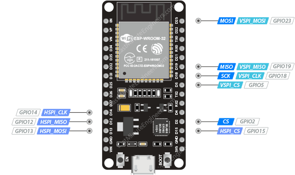
| SPI Channel | MOSI / SDI | MISO / SDO | SCK/CLK | CS/SS |
|---|---|---|---|---|
| VSPI | GPIO23 | GPIO19 | GPIO18 | GPIO5 |
| HSPI | GPIO13 | GPIO12 | GPIO14 | GPIO15 |
We can also define other pins as SPI.
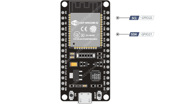
I2C Pins
The ESP32 has a single default I2C bus. The SDA and SCL pins are, by default, assigned to the following pins. However, you can bit-bang the I2C protocol on any GPIO pins with wire.begin(SDA, SCL) command.
UART Pins
ESP32 has 3 UART interfaces, UART0, UART1 and UART2, communicate at up to 5 Mbps.
- UART0 pins are connected to the USB-to-Serial converter and are used for flashing and debugging. It is not recommended to use the UART0 pins.
- UART2, on the other hand, are additional Serial1 pins, and are not connected to the USB-to-Serial converter.
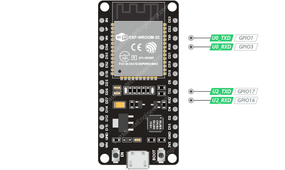
A 499Ω resistor needs to be connected in series on the U0TXD line to suppress the 80 MHz harmonic.
It can also use other pin as TX and RX of UART. Such as below code, define RX to GPIO 26, TX to GPIO 27.
Serial.begin(115200,SERIAL_8N1,26,27);PWM pins
The ESP32 has total 16 PWM (pulse width modulation) channels that can be used to output PWM signals. These PWM channels are labeled 0 through 15 and are connected to various pins on the ESP32. The specific pins that can be used for PWM output depend on the pinout of the ESP32 board you are using.
Here is a list of the pins that can be used for PWM output on the ESP32:
- PWM0: IO4, IO10, IO12, IO13, IO14, IO15, IO27, IO32
- PWM1: IO5, IO9, IO11, IO13, IO15, IO26, IO33
- PWM2: IO6, IO8, IO10, IO12, IO14, IO25, IO34
- PWM3: IO7, IO8, IO9, IO11, IO13, IO24, IO35
The controller consists of PWM timers and the PWM operator. Each timer provides timing in synchronous or independent form, and each PWM operator generates the waveform for one PWM channel.
16 PWM (pulse width modulation) channels that can be used to output PWM signals. These PWM channels are labeled 0 through 15 and are connected to various pins on the ESP32. The specific pins that can be used for PWM output depend on the pinout of the ESP32 board you are using.
Here is a list of the pins that can be used for PWM output on the ESP32:
- PWM0: IO4, IO10, IO12, IO13, IO14, IO15, IO27, IO32
- PWM1: IO5, IO9, IO11, IO13, IO15, IO26, IO33
- PWM2: IO6, IO8, IO10, IO12, IO14, IO25, IO34
- PWM3: IO7, IO8, IO9, IO11, IO13, IO24, IO35