Using a Ball Tilt Sensor with ESP32
Introduction
A ball tilt sensor is a simple but useful device that can detect the orientation or tilt of an object. It finds applications in various fields such as robotics, gaming, and industrial automation. In this post, we will show you how to use a ball tilt sensor with the ESP32 or Arduino.
Working Principle
The ball tilt sensor typically consists of a small enclosed container with a conductive ball inside.
When the sensor is in a vertical direction, the ball will contact two pins. However, when the sensor is in horizontal direction, the connection between two pins are open. So we can use this property to detect the tilt direction.
Electrical Specifications
- Maximum switch rating: <6mA 24VDC
- Electrical life endurance: >50000 cycles
- Contact Resistance: 2Ω (measured at 45° tilt)
Wiring

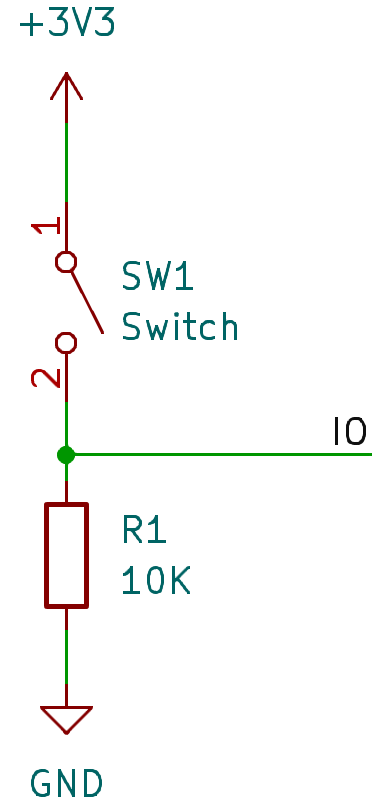
As I measured value, while the ball switch connected the resistor values is about 20Ω. Therefore, we need to use a resistor to limit the current flowing through the sensor. We can use a 10KΩ resistor in series with the sensor to limit the current.
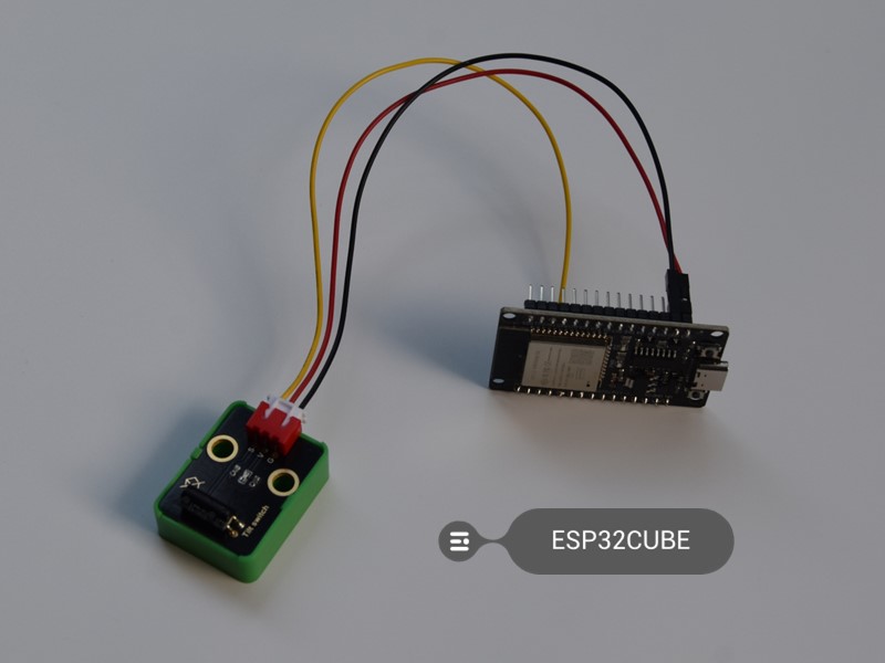
Below picture is the connection between a title switch model, which already provided resistors, so it just need connect to 3.3V, GND, and GPIO.

Then we can use the ESP32's digitalRead() function to read the state of the sensor. When the ball is in the vertical position, the sensor will read HIGH, and when it is in the horizontal position, it will read LOW.
Code (Using PlatformIO)
- First, create a new project in PlatformIO and add the necessary dependencies.
- In the
main.cppfile, include the relevant libraries and define the GPIO pin to which the sensor is connected.
#include <Arduino.h>

// Define the GPIO pin connected to the tilt sensor
const int tiltSensorPin = 25;

void setup() {
  // Initialize the serial communication for debugging (optional but useful)
  Serial.begin(115200);

  // Set the tilt sensor pin as an input
  pinMode(tiltSensorPin, INPUT);
}

void loop() {
  // Read the state of the tilt sensor
  int sensorValue = digitalRead(tiltSensorPin);

  // Print the sensor value to the serial monitor
  Serial.println(sensorValue);

  // Add a delay to avoid reading the sensor too frequently
  delay(100);
}
This code initializes the serial communication for debugging purposes (you can view the sensor readings in the serial monitor). It then configures the GPIO pin connected to the tilt sensor as an input and continuously reads the sensor's state. The value is printed to the serial monitor, and a small delay is added to prevent excessive readings.
Eliminating Signal Jitter
Due to the unstable characteristics of the switch's contact or disconnection, signal jitter can lead to discontinuous output from the sensor. To eliminate signal jitter, we can adopt the following method:
By introducing a delay, we can stabilize the sensor's output to eliminate signal jitter.
#include <Arduino.h>

// Define the GPIO pin connected to the tilt sensor
const int tiltSensorPin = 25;
const unsigned long debounceDelay = 50; // Delay to represent the debounce time in milliseconds
int lastSensorValue = -1; // Store the last stable value read from the sensor

void setup() {
  // Initialize the serial communication for debugging (optional but useful)
  Serial.begin(115200);

  // Set the tilt sensor pin as an input
  pinMode(tiltSensorPin, INPUT);
}

void loop() {
  // Read the state of the tilt sensor
  int sensorValue = digitalRead(tiltSensorPin);

  // If the sensor value is different from the last stable value, wait for the debounce time
  if (sensorValue != lastSensorValue) {
    unsigned long startTime = millis();
    while (millis() - startTime < debounceDelay) {
      // Check if the sensor value has changed during the debounce time
      if (digitalRead(tiltSensorPin) != sensorValue) {
        return; // If the value changed, abort this reading
      }
    }
  }

  // If the code reaches this point, the sensor value has been stable for the debounce time
  if (sensorValue != lastSensorValue) {
    lastSensorValue = sensorValue; // Update the last stable value
    Serial.println(sensorValue); // Print the new stable sensor value to the serial monitor
  }

  // Add a delay to avoid reading the sensor too frequently
  delay(100);
}
Application Scenarios
- Robotics: In robots, the ball tilt sensor can be used to detect if the robot is tilting too much while moving on uneven terrains. This information can be used to adjust the robot's balance or change its movement strategy to prevent it from toppling over.
- Gaming: It can be incorporated into gaming controllers to provide additional input based on the tilt of the controller. For example, in a racing game, tilting the controller can be used to steer the virtual car.
- Industrial Automation: In some industrial processes, such as monitoring the orientation of machinery or containers, the ball tilt sensor can be used to ensure that everything is in the correct position. If a container is tilting too much, it may indicate a problem with the filling process or the stability of the setup.
- Smart Home Devices: In smart home applications, it can be used to detect the orientation of objects like window blinds or lamp.
In conclusion, using a ball tilt sensor with the ESP32 opens up a wide range of possibilities for detecting tilt and orientation in various projects. By understanding its working principle, you can easily integrate it into your applications and enhance their functionality. Whether it's for a fun DIY project or a more serious industrial application, the ball tilt sensor and ESP32 combination can be a valuable addition.
Remember to experiment and customize the code according to your specific requirements. Happy coding!
